工程师 - FTDI SPI converter
中国网站:FTDIChip- 首页
UMFT4222EV-D
UMFT4222EV-D - FTDI
可以下载Datasheet。
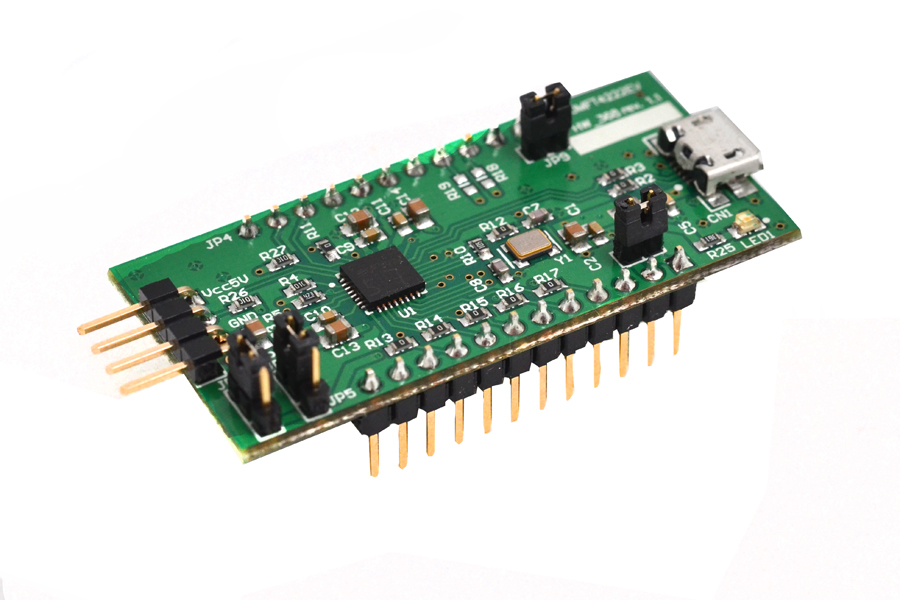
UMFT4222EVUSB2.0 to QuadSPI/I2C Bridge Development Module
Future Technology Devices International Ltd.
The UMFT4222EV is a development module which uses FTDI’s FT4222H, a Hi-Speed USB2.0 to QuadSPI/I2C Bridge in compact 32-pin QFN package. FT4222H requires an external Crystal (12MHz) for the internal PLL to operate. It supports multi-voltage IO, 3.3V, 2.5V or 1.8V. It also provides 128 Bytes one-time-programmable (OTP) memory space for storing vendor specific information. The FT4222H contains SPI/ I2C configurable interfaces. The SPI interface can be configured as master mode with single, dual, or quad bits data width transfer or slave mode with single bit data width transfer. The I2C interface can be configured as master or slave mode.
The UMFT4222EV is supplied as a small PCB which is designed to plug into a standard 0.8” wide 24 pin DIP socket. All components are Pb-free (RoHS compliant).
The UMFT4222EV has the following features:
• Single Hi-Speed USB2.0 chip (FT4222H) to flexible and configurable SPI/I2C interfaces.
• SPI interface support for Single / Dual / Quad SPI Master Mode with configurable target operating speed.
• Up to 28Mbps data transfer rate in SPI mode with quad data mode.
• Support up to 4 slave selection control pins in SPI master mode.
• Support Single SPI Slave Mode with SCK operating frequency up to 20MHz.
• SCK can support up to 40MHz in SPI master.
• I2C interface support 7-bits address and fully compatible to v2.1 and v3 specification for I2C Master/Slave Mode with configurable target operating speed for 100kbit/S standard mode, 400kbit/S fast mode 1Mbit/S Fast mode plus and 3.4Mbit/S high speed mode.
• Configurable GPIOs controlled by application software via USB bus.
• Fully support USB2.0 suspend/resume and remote wakeup.
• Support Battery Charger Detection.
• OTP memory inside for USB Vendor ID (VID), Product ID (PID), device serial number, product description string and various other vendor specific data.
• USB Power Configurations; bus-powered and self-powered.
• On board jumper for FT4222H configuration mode, USB power configuration and VCCIO source selection.
• Integrated power-on-reset circuit.
• True 3.3V CMOS drive output and TTL input. (operates down to 1.8V with external 1.8V power input to VCCIO.
• USB2.0 Low operating and suspend current; 68mA (active-typ.) and 375uA (suspend-typ).
• Configurable I/O pin output drive strength: 4 mA(min) and 16 mA(max).
• UHCI / OHCI / EHCI / XHCI host controller compatible.
• FTDI’s royalty-free Direct (D2XX) drivers eliminate the requirement for USB driver development in most cases.
• Supplied PCB designed to fit a standard 20.2mm (0.8”) wide 24 pin DIP socket. Pins are on a 2.54mm (0.1”) pitch.
• On board USB Micro-B receptacle allows module to be connected to a PC.
1 Typical Applications
• USB to single mode SPI master controller.
• USB to dual mode SPI master controller
• USB to quad mode SPI master controller
• USB to single SPI slave controller
• USB to I2C master interface controller
• USB to I2C slave interface controller
• Utilizing USB to add system modularity
• Incorporate USB interface to enable PC transfers for development system communication.
• USB Industrial Control
• USB Data Acquisition
• USB dongle implementations for Software/ Hardware Encryption and Wireless Modules
• Detect USB dedicated charging ports, to allow for high current battery charging in portable devices
1.1 Driver Support
Royalty free D2XX Direct Drivers are available for the following Operating Systems (OS):
• Windows
• Linux
• Mac
• Android (J2xx / D2xx only)
See the following website link for the full driver support list including OS versions and legacy OS.
Drivers - FTDI
D2XX Direct Drivers allow direct access to the USB device through a DLL. Application software can access the USB device through a series of DLL function calls. A support library for FT4222H, LibFT4222, must be used in conjunction with D2XX and provides high-level and convenient APIs (Application Programming Interface) to speed up user application development. For further details refer to AN_329 User Guide for LibFT4222.
User Guide for LibFT4222
Example code is also provided with the LibFT4222 download. Some D2xx direct functions can be used too. Refer to Appendix B – D2XX API support of AN_329 User Guide for LibFT4222 and reference the D2XX Programmer’s Guide document for details of those APIs which is available from the Documents section of our website.
FT4222H Software Examples - FTDI
D2XX Programmer's Guide
Programming Guides - FTDI
Please also refer to the Installation Guides webpage for details on how to install the drivers.
Installation Guides - FTDI
Please note that there is no VCP interface / drivers for FT4222H. This product can only be used with the D2xx drivers and LibFT4222 library.
1.2 Part Numbers
The following table gives details of the available UMFT4222EV.
Part Number
UMFT4222EV-D
Description
FT4222H evaluation module with D version chip.
1.3 USB Compliant
The UMFT4222EV is fully compliant with the USB 2.0 specification and has been given the USB-IF Test-ID (TID) 10007740.

2 FT4222H Features and Enhancement
Functional Integration: The FT4222H is a USB 2.0 Hi-Speed (480Mbits/s) to flexible and configurable SPI/I2C interfaces device. The FT4222H includes an integrated +1.8V and +3.3V Low Drop-Out (LDO) regulator and a 12MHz to 480MHz PLL. It also includes Power-On-Reset (POR), VBUS detection with 5V-tolerance and 128 bytes one-time-programmable (OTP) memory which simplifies external circuit design and reduces external component count.
USB2.0 Hi-Speed Device Controller: The FT4222H integrates a USB protocol engine which controls the physical Universal Transceiver Macro cell Interface (UTMI) and handles all aspects of the USB 2.0 Hi-Speed interface. The device contains one control endpoint and 4 IN and OUT endpoint pairs. These endpoints can be configured to implement up to 4 independent interfaces/applications mapped to I2C+GPIO or SPI+GPIO.
Highly Integrated USB2.0 to Configurable SPI Bridge: The FT4222H provides the bridge function between a USB2.0 and SPI Master/Slave.
The support library, LibFT4222, based on FTDI’s D2XX driver, enables easy configuration of the SPI as a master or slave. Operating clock frequency on the SPI bus, clock phase and polarity, transfer data bit width mode, and the number of slave selection controls are also configurable.
The max SPI interface operating clock can be set up to 40MHz in master mode and 20MHz in slave mode. With quad mode (4-bits) data bus width, the max data transfer throughput can be up to 28Mbps.
USB to Configurable I2C Controller: The FT4222H also provides the bridge function between a USB2.0 and an I2C Master/Slave.
The support library, LibFT4222, based on FTDI’s D2XX driver, enables easy configuration of the I2C as either a master or slave, including target operating speed and bus protocol on I2C bus.
The device can run at common I2C bus speeds, 100kbit/s standard mode (SM), 400 Kbit/s fast mode (FM), 1 Mbit/s Fast mode plus (FM+), and 3.4 Mbit/s High Speed mode (HS). Clock stretching is also supported to conform to v2.1 and v3.0 of the I2C specification.
Configurable GPIOs: The GPIOs in the FT4222H can be fully controlled by an application utility over USB. There are 4 GPIO pins that can be configured for different purposes, such as a suspend indicator output, and remote wake up input.
The signal drive strength and slew rate can be configured via USB vendor commands for different design needs.
Embedded OTP memory: The internal OTP memory in the FT4222H is used to store USB Vendor ID (VID), Product ID (PID), device serial number, product description string and various other USB configuration descriptors. With this embedded OTP memory, the device can store vendor specific information and save BOM cost. The descriptors can be programmed using the FTDI utility software called FT_PROG, which can be downloaded from FTDI Utilities on the FTDI website.
Utilities - FTDI
Power management: Fully supports USB2.0 suspend/resume and remote wakeup. The PHY will be put to a power saving mode and the clock to most of the digital circuits will be stopped when the device is suspended.
Source Power and Power Consumption: The FT4222H is capable of operating at a voltage supply +3.3V or +5.0V with a nominal operational mode current of 68mA and a nominal USB suspend mode current of 375μA. This allows greater margin for peripheral designs to meet the USB suspend mode current limit of 2.5mA. An integrated level converter within the FT4222H allows the interface logic to run at +1.8V, 2.5V or +3.3V. (Note: External pull-ups are recommended for IO <3V3).
DS_UMFT4222EV.pdf
AN_329_User_Guide_for_LibFT4222-v1.8.pdf
1 Introduction
1.1 Overview
The FT4222H supports 4 operation modes to allow various I2C/SPI devices to be connected to USB bus. The attachable device configuration for each mode is listed below:
•Mode 0 (2 USB interfaces):
▪1 SPI master, SPI slave, I2C master, or I2C slave device
▪1 GPIO device
•Mode 1 (4 USB interfaces):
▪SPI master connects up to 3 SPI slave devices
▪1 GPIO device
•Mode 2 (4 USB interfaces):
▪SPI master connects up to 4 SPI slave devices
•Mode 3 (1 USB interface):
▪1 SPI master, SPI slave, I2C master, or I2C slave device
Operation mode is configured by DCNF0 & DCNF1 pins, please see below table for detail
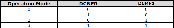
Table 1.1 Chip Mode with DCNF0 and DCNF1
In mode 0 and 3, the connected device can be a SPI/I2C master or slave, depending on how an application developer initializes the FT4222H chip. Mode 1 and mode 2 are designed to connect to multiple SPI slave devices.
The FT4222H can be configured with up to 4 GPIO pins for user applications in mode 0 and mode 1, but each pin is multiplexed with interrupt/suspend out/SPI slave select/I2C functions as listed below:
•gpio0 / ss1o / scl
•gpio1 / ss2o / sda
•gpio2 / ss3o / suspend out
•gpio3 / wakeup/intr
If the FT4222H is initialized as an I2C device, with pins as shown above, the pins of gpio0 and gpio1 will be switched to scl and sda and cannot be used as GPIO.
By default, the pin for gpio2 is configured as suspend out, and the pin for gpio3 is configured as wakeup/intr. Only those configured GPIO pins can support GPIO read/set operation through the corresponding endpoint.
1.2 Scope
The guide is intended for developers who are creating applications, extending FTDI provided applications or implementing FTDI’s applications for the FT4222H.
2 Getting Started
3 Application Programming Interface (API)
3.1 Typedefs
3.2 FT4222 General Functions
3.2.1 Open and Close
3.2.2 Un-initialize
3.2.3 Set Clock
3.2.4 Get Clock
3.2.5 Set Suspend Out
3.2.6 Set Wake Up/Interrupt
3.2.7 Set Interrupt Trigger Condition
3.2.8 Get Max Transfer Size
3.2.9 Set Event Notification
Sets conditions for event notification.
An application can use this function to set up conditions which allow a thread to block until one of the conditions is met. Typically, an application will create an event, call this function, and then block on the event. When the conditions are met, the event is set, and the application thread unblocked. Usually, the event is set to notify the application to check the condition. The application needs to check the condition again before it goes to handle the condition. The API is only valid when the device acts as SPI slave and SPI slave protocol is not SPI_SLAVE_NO_PROTOCOL.
Currently, this function only supports the event below:
- FT4222_EVENT_RXCHAR The event will be set when a data packet has been received by the device.
3.2.10 Get Version
3.2.11 Chip Reset
3.2.12 Get Chip Mode
3.3 SPI Master Functions
For SPI Master Single mode, all data packets are terminated with a zero-length packet. Therefore, after one data packet there will be one SOF then follows by the terminating zero-length packet then ends with another SOF. As a result, under normal conditions, these two SOF’s will take approximately 250us.
3.3.1 SPI Master Init
Initialize the FT4222H as an SPI master.
To support various types of SPI slave devices, the FT4222H SPI master is configurable using the following parameters:
•IO lines: SPI transmission lines. The FT4222H SPI supports single, dual, or quad transmission mode. An application may override this initial selection dynamically using FT4222_SPIMaster_SetLines. For example, commands might be sent in single mode, but data transferred in dual or quad mode.
•Clock divider: SPI clock rate is subject to system clock. The FT4222H SPI clock could be 1/2, 1/4, 1/8, 1/16, 1/32, 1/64, 1/128, 1/256, or 1/512 system clock rate.
•Clock polarity: Idle high or idle low.
•Clock phase: Data is sampled on the leading (first) or trailing (second) clock edge.
•Slave selection output pins: Select slave devices by ss0o, ss1o, ss2o, ss3o. The default slave selection is active low.
•There is only one setting stored in the MCU. If there are multi-SPI masters to be initialized, keep all settings the same, including ssoMap.
3.3.2 SPI Master Set Lines
3.3.3 SPI Master Set Mode
3.3.4 SPI Master Set Chip Select
3.3.5 SPI Master Single Read
3.3.6 SPI Master Single Write
3.3.7 SPI Master Single Read and Write
Under SPI single mode, full-duplex write data to and read data from an SPI slave.
The standard SPI protocol simultaneously sends data onto the MOSI data line and receives data from the MISO line.
| uint8 sendData[2]; sendData[0] = 0x05; // read status command ft4222Status = FT4222_SPIMaster_SingleReadWrite(ftHandle, &readData[0], &sendData[0], 2, &sizeTransferred, true); |
3.3.8 SPI Master Multi Read and Write
Under SPI dual or quad mode, write data to and read data from an SPI slave.
Figure 3.2 illustrates the dual-SPI protocol supported by the FT4222H SPI master. It is a mixed protocol initiated with a single write transmission, which may be an SPI command and dummy cycles, and followed by dual-write and dual-read transmission that use 2 signals in parallel for the data. All three parts of the protocol are optional. For example, developers can ignore the multi-read part by setting multiReadBytes=0.
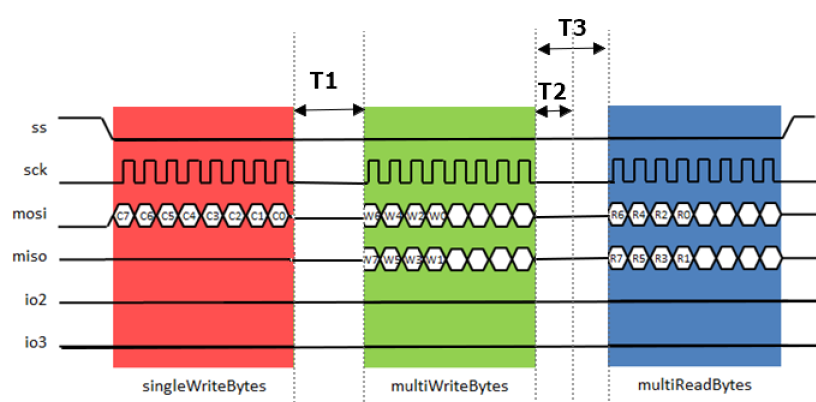
Figure 3.2 Dual SPI communications
Avoid I/O conflict from multiWriteBytes state to multiReadBytes state. When SPI finishes multiWriteBytes state, I/O pins (Dual mode:mosi/miso, Quad mode:mosi/miso/io2/io3) will keep the output state for T2 period of time and then change to input state.
This table only takes effect on CLK division >=8. If CLK division is equal to 2 or 4, the time for T2 and T3 is very close and SPI Slave is hard to switch the I/O in such a short time.
3.4 SPI Slave Functions
The FT4222H can be initialized as an SPI slave under mode 0 to mode 3. As an SPI slave, the FT4222H only supports the standard single SPI transfer.
SPI Slave function is not suitable on Android system. Garbage collection is a form of automatic memory management. When garbage collection happens, it does not emit bulk-in packet and RX data may be lost during this period of time.
A USB-SPI bridge usually faces the challenge that USB cannot guarantee the throughput for each endpoint, but SPI requires data transmission at a steady rate. It is highly possible when an SPI master starts to request data from a USB-SPI slave bridge device, the data has not arrived from the USB host side yet. In addition, SPI does not have a standard protocol to allow the master side to check the status of the slave side. The protocol is usually provided by an SPI slave device on its own, which makes the SPI master device communicate with the slave device by its specified commands.
There are three methods to access FT4222 SPI Slave function.
•SPI_SLAVE_WITH_PROTOCOL
•SPI_SLAVE_NO_ACK
•SPI_SLAVE_NO_PROTOCOL
With all the SPI Slave operational modes listed, the support library will always add a dummy byte of “0x00” as the first byte for every transmission. This is an internal sync byte that is needs to be removed by the SPI Master.
SPI_SLAVE_WITH_PROTOCOL
The FT4222H and LibFT4222 design have implemented an SPI slave protocol which must be used to handle the integrity of data transmission. The API “FT4222_SPISlave_Init” is used to initialize the slave with this mode.
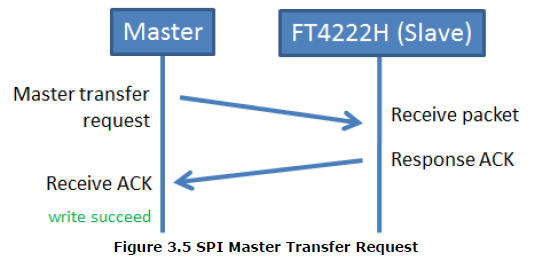
In this protocol, a master starts an SPI transaction by sending a packet in the format illustrated below. The Sync Word “0x5A” is fixed with this slave mode and user applications do not need to do any operations to add or remove the Sync Word. It is done by the support library.
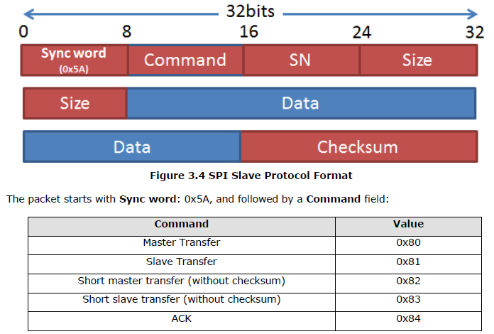
SN stands for serial number. It is monotonically increased and helps to identify packets. Size is a two-byte field, which is the size of the data field in big-endian order. The Checksum is the summation of all data fields’ lower two bytes starting from the first byte, the sync word, to the latest data byte.
The checksum is in big-endian order as well. When the slave, FT4222H, receives the transfer request from the master, it will respond with an ACK. The master can confirm the transaction succeeded when it receives the ACK from the slave.
When SPI Slave receives the Master transfer request, it will check if the format and checksum are correct. If the answer is yes, the support-lib will send the response ACK automatically, grab the data from the packet and send it to application.
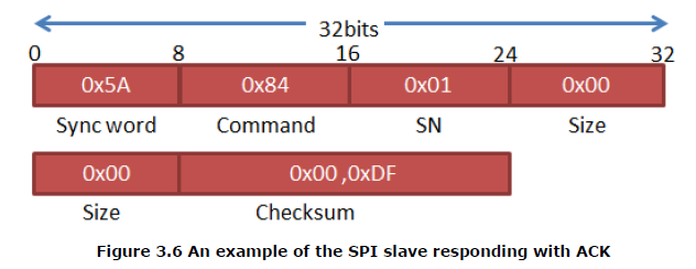
Here is an example of an ACK packet. The SN field of the ACK packet identifies which request it corresponds to. An ACK packet has no data therefore the Size field should be 0.
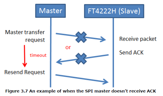
If the SPI master does not receive the ACK response from the slave, it should send its request again.
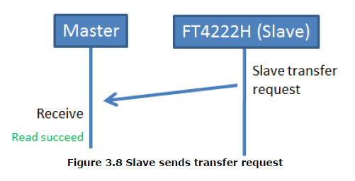
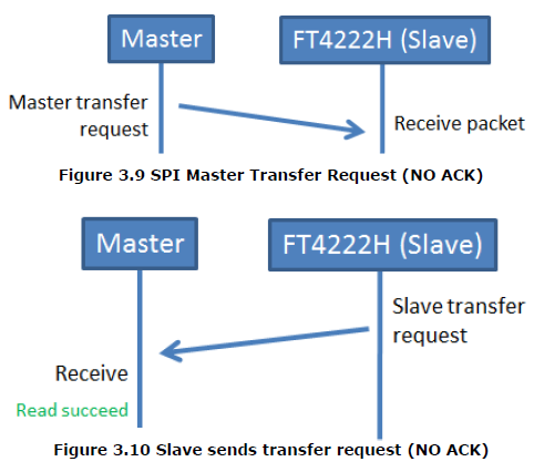
When the FT4222H SPI slave wants to send data to the master, which may be requested by the master, it just sends a transfer request in the same protocol format as shown in Figure 3.4.
In this case, it is not necessary to append any header while API FT4222_SPISlave_Write is called.
The encapsulation of header is done by support-lib.
SPI_SLAVE_NO_ACK
This option is to reduce the complication of SPI_SLAVE_WITH PROTOCOL.
It removes the ACK response from the Slave.
SPI_SLAVE_NO_PROTOCOL
This option provides no protocol for SPI Slave function, and it is configured and initialized with the API FT4222_SPISlave_InitEx.
In this SPI Slave operational mode, the Sync Word “0x5A” is not inserted. And there is no additional process in support-lib.
Users can design own protocol(s) to communicate with a SPI master.
3.4.1 SPI Slave Init
Parameters:
ftHandle, Handle of the device.
Return Value:
FT4222_OK if successful, otherwise the return value is an FT error code.
3.4.2 SPI Slave Init extend function
Parameters:
ftHandle, Handle of the device.
protocolOpt,
SPI SLAVE protocol could be:
•SPI_SLAVE_WITH_PROTOCOL
With the full SPI SLAVE PROTOCOL supported. Refer to chapter 3.4
•SPI_SLAVE_NO_PROTOCOL
Remove SPI SLAVE protocol, users can design their own protocol.
•SPI_SLAVE_NO_ACK
Retain SPI SLAVE protocol but remove command ‘ACK’
3.4.3 SPI Slave Set mode function
Set SPI slave CPOL and CPHA. The Default value of CPOL is CLK_IDLE_LOW, default value of CPHA is CLK_LEADING.
3.4.4 SPI Slave Get Rx Status
3.4.5 SPI Slave Read
3.4.6 SPI Slave Write
3.5 SPI General Functions
3.5.1 SPI Reset Transaction
Reset the SPI transaction. It would purge receive and transmit buffers in the device and reset the transaction state. D2XX has a similar function (FT_PURGE) but strongly recommend to use FT4222_SPI_ResetTransaction.
3.5.2 SPI Reset
Reset the SPI master or slave device. If the SPI bus encounters errors or works abnormally, this function will reset the SPI device. It is not necessary to call SPI init function again after calling this reset function. It remains all original setting of SPI.
3.5.3 SPI Set Driving Strength
For the FT4222H SPI, set the driving strength of clk, io, and sso pins. The default driving strength of all SPI pins are 4MA. DS_4MA is adopted mostly. Unless there is some hardware wiring requirement for device, set driving strength to 4MA is enough.
3.6 I2C Master Functions
I2C (Inter Integrated Circuit) is a multi-master serial bus invented by Philips. I2C uses two bi-directional open-drain wires called serial data (SDA) and serial clock (SCL). Common I²C bus speeds are the 100 kbit/s standard mode (SM), 400 kbit/s fast mode (FM), 1 Mbit/s Fast mode plus (FM+), and 3.4 Mbit/s High Speed mode (HS)
The FT4222H device can be initialized as either an I2C master or I2C slave under mode 0 and mode 3. Here is a brief overview of FT4222H I2C features:
•Fully compatible to I2C v2.1 and v3 specification
•7-bit address support
•Support 4 speed configurations: 100KHz(SM), 400KHz(FM), 1MHz(FM+), and 3.4MHz(HS).
•Clock stretching support in both master and slave mode.
3.6.1 I2C Master Init
3.6.2 I2C Master Read
3.6.3 I2C Master Write
3.6.4 I2C Master Write Extension
I²C defines basic types of transactions, each of which begins with a START and ends with a STOP:
• Single message where a master writes data to a slave.
• Single message where a master reads data from a slave.
• Combined format, where a master issues at least two reads or writes to one or more slaves.
In a combined transaction, each read or write begins with a START and the slave address. The START conditions after the first are also called repeated START bits. Repeated STARTs are not preceded by STOP conditions, which is how slaves know that the next message is part of the same transaction.
3.6.5 I2C Master Read Extension
Read data from the specified I2C slave device with the specified I2C condition.
This function is supported by the Revision B FT4222H or later.
I²C combined message support
In a combined message, each read or write begins with a START and the slave address. After the first START, the subsequent starts are referred to as repeated START bits; repeated START bits are not preceded by STOP bits, which indicate to the slave the next transfer is part of the same message.

SR = repeated START condition
3.6.6 I2C Master GetStatus
Read the status of the I2C master controller. This can be used to poll a slave after I2C transmission is complete.
controllerStatus
Address of byte to receive status flags:
bit 0: controller busy: all other status bits invalid
bit 1: error condition
bit 2: slave address was not acknowledged during last operation
bit 3: data not acknowledged during last operation
bit 4: arbitration lost during last operation
bit 5: controller idle
bit 6: bus busy
The header file provides convenience macros (such as I2CM_BUS_BUSY) to test these bits.
3.6.7 I2C Master Reset
Reset the I2C master device.
If the I2C bus encounters errors or works abnormally, this function will reset the I2C device. It is not necessary to call I2CMaster_Init again after calling this reset function. This function will maintain the original I2C master setting and clear all cache in the device. D2XX has a similar function (FT_PURGE) but strongly recommend to use FT4222_I2CMaster_Reset.
3.6.8 I2C Master Reset Bus
If the data line (SDA) is pulled LOW by slave device, this API will send nine SCK clocks from master to recover I2C bus. The slave device will release data line (SDA) when it receives the nine clocks from master. If data line cannot be released by this API, HW reset or cycle power is another solution.
3.7 I2C Slave Functions
The FT4222H device can be initialized as an I2C slave under mode 0 and mode 3. It conforms to v2.1 and v3.0 of the I2C specification and supports all the transmission modes: Standard, Fast, Fast-plus and High Speed.
When the I2C slave receives data from the I2C bus, it will keep the data in its internal receive buffer (256 bytes), and then send the data to the USB host through IN packets.
When data is requested by an I2C master, data will be moved from an OUT packet to the transmit register directly.
3.7.1 I2C Slave Init
Initialize FT4222H as an I2C slave. After FT4222_I2CSlave_Init, I2C slave address is reset to 0x40.
3.7.2 I2C Slave Get Address
3.7.3 I2C Slave Set Address
3.7.4 I2C Slave Get Rx Status
3.7.5 I2C Slave Read
3.7.6 I2C Slave Write
Write data to the buffer of I2C slave device.
3.7.7 I2C Slave Reset
3.7.8 I2C Slave Clock Stretch
Enable or disable Clock Stretch. The default setting of clock stretching is disabled.
Clock stretch is as a flow-control mechanism for slaves. An addressed slave device may hold the clock line (SCL) low after receiving (or sending) a byte, indicating that it is not yet ready to process more data. The master that is communicating with the slave may not finish the transmission of the current bit but must wait until the clock line goes high.
3.7.9 I2C Slave Set Response Word
This function only takes effect when Clock Stretch is disabled. When data is requested by an I2C master and the device is not ready to respond, the device will respond a default value. Default value is 0xFF. This function can be used to set the response word.
3.8 GPIO Functions
The FT4222H contains 4 GPIO. When the USB GPIO interface is supported, chip mode 0 and mode 1, LibFT4222 helps application developers to control GPIO directly. However, each GPIO pin is multiplexed with interrupt/suspend out/SPI slave select/I2C functions as listed below:
•gpio0 / ss1o / scl
•gpio1 / ss2o / sda
•gpio2 / ss3o / suspend out
•gpio3 / wakeup/intr
3.8.1 GPIO Init
3.8.2 GPIO Read
3.8.3 GPIO Write
3.8.4 GPIO Set Input Trigger
3.8.5 GPIO Get Trigger Status
3.8.7 GPIO Set WaveForm Mode
3.8.6 GPIO Read Trigger Queue
3.8.7 GPIO Set WaveForm Mode
4 Contact Information
Head Office
Branch Office
Appendix A – Enumeration and Structure Definitions
Enumeration
FT4222_STATUS
FT4222_ClockRate
FT4222_SPIMode
FT4222_SPIClock
Structure Definitions
struct FT4222_Version
{
DWORD chipVersion; // The version of FT4222H chip
DWORD dllVersion; // The version of LibFT4222
};
struct SPI_Slave_Header
{
uint8 syncWord;
uint8 cmd;
uint8 sn;
uint16 size;
};
Appendix B – D2XX API support
D2XX supported API
Appendix C – References
Document References
DS_FT4222H USB IC Data Sheets - FTDI
D2XX Programmers Guide Programming Guides - FTDI
D2XX Drivers D2XX Drivers - FTDI
FT_PROG Utilities - FTDI
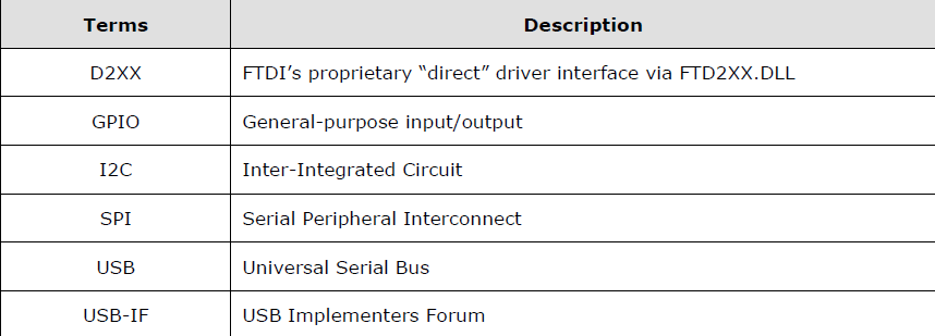
Acronyms and Abbreviations
Appendix D – List of Tables and Figures
List of Tables
List of Figures
Appendix E – Revision History
Revision Changes Date
1.0 Initial Release. 16-09-2014
......
1.8 Add Section 3.2.12 Get Chip Mode. 12-03-2024
拿两个同样的板子,用来进行I2C和SPI的互相通讯。或者多个板子用来做SPI slave片选模拟。作为教学使用不错。
FTD也有一些其他开发板。
作为SPI master,测试起来方便一些,直接设置工作频率,然后输出数据,使用逻辑分析仪查看波形。Get Max Transfer Size 这个 API可以调用一下,看最大的传输包大小。
相关文章:

工程师 - FTDI SPI converter
中国网站:FTDIChip- 首页 UMFT4222EV-D UMFT4222EV-D - FTDI 可以下载Datasheet。 UMFT4222EVUSB2.0 to QuadSPI/I2C Bridge Development Module Future Technology Devices International Ltd. The UMFT4222EV is a development module which uses FTDI’s FT4222H…...
)
河畔石上数(C++)
在 C 里,std::set 是标准模板库(STL)提供的一种关联容器,它能高效地存储唯一元素,并且元素会按照特定的顺序排列,默认是升序。下面从多个方面为你详细介绍 std::set。 1. 头文件包含 若要使用 std::set&a…...
)
《线性表、顺序表与链表》教案(C语言版本)
🌟 各位看官好,我是maomi_9526! 🌍 种一棵树最好是十年前,其次是现在! 🚀 今天来学习C语言的相关知识。 👍 如果觉得这篇文章有帮助,欢迎您一键三连,分享给更…...

【用Cursor 进行Coding 】
「我」:“添加 XXX 功能” [Claude-3.7]:“好的,我完成了,还顺手做了 19个你没要求不需要的功能、甚至还修改了原有999行正常代码 ~ 不用谢” [Gemini-2.5]:“好的,我会…...

vue2 打包时增加时间戳防止浏览器缓存,打包后文件进行 js、css 压缩
文章目录 前言一、什么是浏览器缓存二、展示效果三、vue.config.js 代码四、代码压缩部分服务器不支持五、感谢 前言 vue 开发过程中,项目前端代码需要更新,更新后由于浏览器缓存导致代码没有及时更新所产生错误,所以在打包时增加时间戳防止…...

TIM定时器
一、TIM定时器 STM32高级定时器实战:PWM、捕获与死区控制详解-CSDN博客 二、相关函数 1.TIM_TimeBaseInitTypeDef结构体讲解 typedef struct {uint16_t TIM_Prescaler; // 预分频器,用于设置定时器计数频率uint16_t TIM_CounterMode; /…...

S130N-ISI 全栈方案与云平台深度协同:重构 PLC 开发新范式
一、什么是 PLC? 1.技术定义 PLC(Power Line Communication)是一种创新的通信技术,它以电力线作为天然的传输介质,通过先进的信号调制技术将高频数据信号叠加于工频电流之上,实现电力输送与数据通信的双频共…...

Jenkins 插件文件优先使用 .jpi 后缀
.hpi 和 .jpi 文件本质上是 Jenkins 插件的打包格式,两者的区别主要体现在历史和命名习惯上: ✅ .hpi(Hudson Plugin) 来源:最初是 Hudson 项目的插件格式。含义:Hudson Plugin 的缩写。用途:早…...

# 决策树与PCA降维在电信客户流失预测中的应用
决策树与PCA降维在电信客户流失预测中的应用 在数据分析和机器学习领域,电信客户流失预测是一个经典的案例。本文将通过Python代码实现,探讨决策树模型在电信客户流失预测中的应用,并结合PCA降维技术优化模型性能,同时对比降维前…...

go语言的语法糖以及和Java的区别
1. Go 语言的语法糖及简化语法 Go 语言本身设计理念是简洁、清晰,虽然不像某些动态语言那样“花哨”,但它提供了几种便捷语法,使代码更简洁: 1.1 短变量声明(Short Variable Declaration) 语法࿱…...

WebRtc 视频流卡顿黑屏解决方案
// node webrtc视频转码服务 const url "http://10.169.xx.xx:8000" <video :ref"videoRefs${index}" :id"videoRefs4_${index}" :src"item" controls:key"item" autoplay muted click"preventDefaultClick"…...

信息安全测评中心-国产化!
项目上使用产品,必须通过国家信息安全测评/ 信息技术产品安全测评,有这个需求的话,可以到CN信息安全测评中心官网中的--测评公告一栏中,找符合要求的产品。 测评公告展示的包括硬件产品、系统、服务资质等。 网址及路径…...

MySQL学习笔记九
第十一章使用数据处理函数 11.1函数 SQL支持函数来处理数据但是函数的可移植性没有SQL强。 11.2使用函数 11.2.1文本处理函数 输入: SELECT vend_name,UPPER(vend_name) AS vend_name_upcase FROM vendors ORDER BY vend_name; 输出: 说明&#…...

DFS 蓝桥杯
最大数字 问题描述 给定一个正整数 NN 。你可以对 NN 的任意一位数字执行任意次以下 2 种操 作: 将该位数字加 1 。如果该位数字已经是 9 , 加 1 之后变成 0 。 将该位数字减 1 。如果该位数字已经是 0 , 减 1 之后变成 9 。 你现在总共可以执行 1 号操作不超过 A…...
)
动态规划dp专题-(上)
目录 dp理论知识🔥🔥 🎯一、线性DP (1)🚀斐波那契数 -入门级 (2)🚀898. 数字三角形-acwing ---入门级 (3)往期题目 ①选数异或:在…...
)
正则表达式(一)
一、模式(Patterns)和修饰符(flags) 通过正则表达式,我们可以在文本中进行搜索和替换操作,也可以和字符串方法结合使用。 正则表达式 正则表达式(可叫作 “regexp”,或 “reg”&…...

需求变更导致成本超支,如何止损
需求变更导致成本超支时,可以通过加强需求管理、严格的变更控制流程、优化资源配置、实施敏捷开发、提高风险管理意识等方法有效止损。其中,加强需求管理是止损的核心措施之一。需求管理涉及需求明确化、需求跟踪和变更的管理,有效的需求管理…...
ch5-实训代码)
《数据分析与可视化》(清华)ch5-实训代码
小费数据集预处理——求思考题_有问必答-CSDN问答 以上代码在Jupyter Notebook中可以运行,但是在python中就会出如下问题: 这个错误表明在尝试计算均值填充缺失值时,数据中包含非数值类型的列(如文本列),…...

E: The package APP needs to be reinstalled, but I can‘t find an archive for it.
要解决错误 “E: The package mytest needs to be reinstalled, but I can’t find an archive for it”,通常是因为系统中存在损坏的软件包记录或安装过程中断导致 /var/lib/dpkg/status 文件异常。以下是综合多篇搜索结果的解决方案: 解决步骤 备份关…...
详解)
若依startPage()详解
背景 startPage基于PageHelper来进行强化,在用户传入pagesize,pageNum等标准参数的时候不需要进行解析 步骤 1.通过ServletUtils工具类getRequestAttributes来获取当前线程的上下文信息 public static ServletRequestAttributes getRequestAttributes() {try {R…...

Oracle AQ
Oracle AQ(Advanced Queuing) 是 Oracle 数据库内置的一种消息队列(Message Queue)技术,用于在应用或系统之间实现异步通信、可靠的消息传递和事件驱动架构。它是 Oracle 数据库的核心功能之一,无需依赖外部…...

npm报错CERT_HAS_EXPIRED解决方案
npm报错解决方案 npm ERR! code CERT_HAS_EXPIRED npm ERR! errno CERT_HAS_EXPIRED方案1:尝试切换镜像 # 使用腾讯云镜像 npm config set registry https://mirrors.cloud.tencent.com/npm/# 或使用官方npm源(科学上网) npm config set registry http…...

pnpm 中 Next.js 模块无法找到问题解决
问题概述 项目在使用 pnpm 管理依赖时,出现了 “Cannot find module ‘next/link’ or its corresponding type declarations” 的错误。这是因为 pnpm 的软链接机制在某些情况下可能导致模块路径解析问题。 问题诊断 通过命令 pnpm list next 确认项目已安装 Next.js 15.2.…...

急速实现Anaconda/Miniforge虚拟环境的克隆和迁移
目录 参考资料 点击Anaconda Prompt (anaconda_base) 查看现有环境 开始克隆,以克隆pandas_env为例,新的环境名字为image (base) C:\Users\hello>conda create -n image --clone pandas_env查看克隆结果,image环境赫然在列。 然后粘贴…...
——图像的掩膜)
OpenCv高阶(二)——图像的掩膜
目录 掩膜 bitwise_and原理 掩膜的实现 1、基于像素操作 2、使用形态学操作 3、基于阈值处理 案例 1、读取原图并绘制掩膜 2、掩膜的实现 3、绘制掩膜的直方图 应用 掩膜 OpenCV 中图像掩膜(Mask)实现的原理是通过一个与原始图像大小相同的二…...
--最小生成树)
数据结构和算法(十二)--最小生成树
一、最小生成树 定义:图的生成树是它的一颗含有其所有顶点的无环连通子图,一副加权无向图的最小生成树它的一颗权值(树中所有边的权重之和)最小的生成树。 约定:只考虑连通图。最小生成树的定义说明它只能存在于连通图…...

开源酷炫的Linux监控工具:sampler
sampler是一个开源的监控工具,来自GitHub用户sqshq(Alexander Lukyanchikov)的匠心之作。 简单来说,sampler能干这些事儿: 实时监控:CPU、内存、磁盘、网络,甚至应用程序的状态,它…...

InternVideo2.5:Empowering Video MLLMs with Long and Rich Context Modeling
一、TL;DR InternVideo2.5通过LRC建模来提升MLLM的性能。层次化token压缩和任务偏好优化(mask时空 head)整合到一个框架中,并通过自适应层次化token压缩来开发紧凑的时空表征MVBench/Perception Test/EgoSchema/MLVU数据benchmar…...

OSPF基础与特性
一.OSPF 的技术背景 OSPF出现是因为RIP协议无法满足大型网络的配置 RIP协议中存在的问题 RIP中存在最大跳数为15的限制,不能适应大规模组网 RIP周期性发送全部路由信息,占用大量的带宽资源 路由收敛速度慢 以跳数作为度量衡,选路可能会不优 存在路由环路的可能性 每隔30秒更新…...

[Linux]从零开始的ARM Linux交叉编译与.so文件链接教程
一、前言 最近在项目需要将C版本的opencv集成到原本的代码中从而进行一些简单的图像处理。但是在这其中遇到了一些问题,首先就是原本的opencv我们需要在x86的架构上进行编译然后将其集成到我们的项目中,这里我们到底应该将opencv编译为x86架构的还是编译…...

golang 中 make 和 new 的区别?
在Go语言中,make 和 new 都是用于内存分配的关键字,但它们在使用场景、返回值和初始化方式等方面存在一些区别,以下是具体分析: 使用场景 make 只能用于创建 map、slice 和 channel 这三种引用类型,用于初始化这些类型…...

碧螺春是绿茶还是红茶
碧螺春是绿茶,不是红茶。 碧螺春的特点: 类别: 碧螺春属于中国六大茶类中的绿茶类。产地: 它产自中国江苏省苏州市太湖的东山和西山(现称金庭镇),是中国十大名茶之一。外形: 碧螺春茶叶外形卷曲如螺,色泽…...

Linux平台搭建MQTT测试环境
Paho MQTT Paho MQTT 是 Eclipse 基金会下的一个开源项目,旨在为多种编程语言提供 MQTT 协议的客户端实现。MQTT(Message Queuing Telemetry Transport)是一种轻量级的发布/订阅(Pub/Sub)消息传输协议ÿ…...
)
【AI学习】AI Agent(人工智能体)
1,AI agent 1)定义 是一种能够感知环境、基于所感知到的信息进行推理和决策,并通过执行相应动作来影响环境、进而实现特定目标的智能实体。 它整合了多种人工智能技术,具备自主学习、自主行动以及与外界交互的能力,旨…...
安装与注册完整教程 - Windows/macOS双平台指南)
克魔助手(Kemob)安装与注册完整教程 - Windows/macOS双平台指南
iOS设备管理工具克魔助手便携版使用全指南 前言:为什么需要专业的iOS管理工具 在iOS开发和设备管理过程中,开发者经常需要突破系统限制,实现更深层次的控制和调试。本文将详细介绍一款实用的便携式工具的使用方法,帮助开发者快速…...

了解GPIO对应的主要功能
GPIO GPIO是通用输入输出端口的简称,芯片上的GPIO引脚与外部设备连接实现通讯、控制以及数据采集等功能,最基本的输出功能是通过控制引脚输出高低电平继而实现开关控制,比如引脚接入LED灯可控制LED灯的亮灭,接入继电器或三极管可…...

Dubbo 注册中心与服务发现
注册中心与服务发现 注册中心概述 注册中心是dubbo服务治理的核心组件,Dubbo依赖注册中心的协调实现服务发现,自动化的服务发现是微服务实现动态扩容、负载均衡、流量治理的基础。 Dubbo的服务发现机制经历了Dubbo2时代的接口级服务发现、Dubbo3时代的…...

一文详解LibTorch环境搭建:Ubuntu20.4配置LibTorch CUDA与cuDNN开发环境
随着深度学习技术的迅猛发展,越来越多的应用程序开始集成深度学习模型以提供智能化服务。为了满足这一需求,开发者们不仅依赖于Python等高级编程语言提供的便捷框架,也开始探索如何将这些模型与C应用程序相结合,以便在性能关键型应…...

micro ubuntu 安装教程
micro ubuntu 安装教程 官网地址 : https://micro-editor.github.io 以下是在 Ubuntu 系统中安装 micro 编辑器 的详细教程: 方法 1:通过 apt 直接安装(推荐) 适用于 Ubuntu 20.04 及以上版本(官方仓库已收录…...

观成科技:利用DoH加密信道的C2流量分析
概述 DoH(DNS over HTTPS)是一种通过HTTPS协议加密传输DNS查询的信道,将DNS请求封装在HTTP/2或HTTP/3中,DoH没有标准端口,部分服务沿用TLS的443端口。传统DNS明文传输易被拦截或篡改,而DoH通过加密提升了隐…...

行星际空间的磁流体动力激波:理论综述
Magnetohydrodynamic Shocks in the Interplanetary Space: a Theoretical Review ( Part 2 ) Magnetohydrodynamic Shocks in the Interplanetary Space: a Theoretical Review | Brazilian Journal of Physics Magnetohydrodynamic Shocks 1. The Rankine-Hu…...

Java垃圾回收的隐性杀手:过早晋升的识别与优化实战
目录 一、现象与症状 二、过早晋升的成因 (一)Young区(Eden区)配置过小 (二)分配速率过高 (三)晋升年龄阈值(MaxTenuringThreshold)配置不当 三、动态晋…...

2noise团队开源ChatTTS,支持多语言、流式合成、语音的情感、停顿和语调控制
简介 ChatTTS 是一个开源的文本转语音(Text-to-Speech, TTS)项目,由 2noise 团队开发,专门为对话场景设计。它在 GitHub 上广受欢迎,因其自然流畅的语音合成能力和多功能性而备受关注。 项目背景 目标:设计…...

企业级防火墙与NAT网关配置
实训背景 某公司需部署一台Linux网关服务器,要求实现以下功能: 基础防火墙:仅允许SSH(22)、HTTP(80)、HTTPS(443)入站,拒绝其他所有流量。共享上网…...

AI数据分析的正道是AI+BI,而不是ChatBI
一、AI大模型在数据分析中的应用现状与局限 当前用户直接上传PDF、Excel等原始数据至AI大模型进行自动分析的趋势显著,但其技术成熟度与落地效果仍需审慎评估。 1.主流AI大模型的数据分析能力对比 GPT-4/Claude 3系列:在通用数据分析任务中表现突出&a…...

C++设计模式优化实战:提升项目性能与效率
🧑 博主简介:CSDN博客专家、CSDN平台优质创作者,高级开发工程师,数学专业,拥有高级工程师证书;擅长C/C、C#等开发语言,熟悉Java常用开发技术,能熟练应用常用数据库SQL server,Oracle…...

G1学习打卡
🍨 本文为🔗365天深度学习训练营 中的学习记录博客🍖 原作者:K同学啊 import argparse import os import numpy as np import torchvision.transforms as transforms from torchvision.utils import save_image from torch.utils.…...

8.2 对话框2
版权声明:本文为博主原创文章,转载请在显著位置标明本文出处以及作者网名,未经作者允许不得用于商业目的 8.2.3 FolderBrowserDialog(文件夹对话框) 组件 FolderBrowserDialog组件,用于选择文件夹 Folder…...
:操作与实现详解)
Java中的列表(List):操作与实现详解
引言 列表(List)是Java集合框架中最基础且使用最频繁的线性数据结构。它允许有序存储元素,支持重复值和快速访问。本文将深入探讨Java列表的核心操作方法,并剖析两种经典实现类(ArrayList和LinkedList)的底…...

在kotlin的安卓项目中使用dagger
在 Kotlin 的 Android 项目中使用 Dagger(特别是 Dagger Hilt,官方推荐的简化版)进行依赖注入(DI)可以大幅提升代码的可测试性和模块化程度。 1. 配置 Dagger Hilt 1.1 添加依赖 在 bu…...